
Applications Knowledge
Explore the Edgevision
Visual examination (VT) and RVI
Most effective and informative method
Used to examine boiler tubes, headers, drums, and piping.
Used to examine internal and external surfaces.
Commonly used in the detection of most forms of boiler pressurepart damage.
The root cause method has been used extensively for the failure analysis of boiler tubing. The root cause of failure is defined as the circumstances that allow a failure mechanism to operate, that is, the reason for the failure occurred. It is important to determine the root cause in order to take corrective action. Applying the appropriate NDE methods to each of the components and damage mechanisms is the key to maintaining safe continued operation.
Timely NDE can save money by allowing the boiler operator to take these actions:
- Monitor problematic areas for signs of incipient damage
- Modify operating or maintenance procedures to lessen developing damage
- Proactively schedule outages to deal with a developing problem rather than being forced into an expensive unplanned outage — Monitor the effectiveness of implemented actions
Recognizing Damage Types
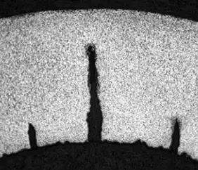
Corrosion Fatigue
Summary/Appearance
Inside surface: Multiple, parallel cracks, often associated with corrosion pits or surface discontinuities, can be either axial or circumferential, but cracks are oriented normal to the predominant tensile stress.
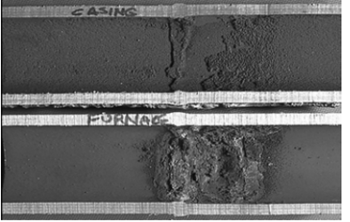
Hydrogen Damage
Summary/Appearance
Inside surface: Gouged areas and/or thick deposits, along with localized internal deposition, wall loss, pitting, or gouging, may or may not be present beneath the deposits.
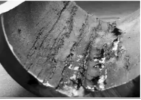
Acid Phosphate Corrosion
Summary/Appearance
Inside surface: Gouges, partially or completely filled with layered deposits, may be present on the inside surface, often with a distinct transition between mild and severe corrosion.
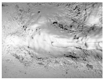
Caustic Gouging
Summary/Appearance
Inside surface: The surface may exhibit internal hemispherical or elliptical depressions, partially or completely filled with thick layered deposits.
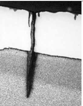
Thermal Fatigue in Waterwalls
Summary/Appearance
Outer surface: In cross-section, the cracks are sharp, vee-shaped, or finger-like and are primarily transgranular in nature.
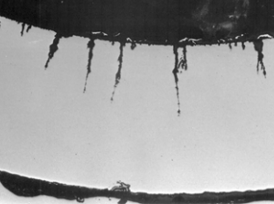
Thermal Fatigue in Economizer Header Tubes
Summary/Appearance
Inside surface: The damaged stub tube will manifest numerous longitudinal cracks. The cracks may be distributed completely around the bore of the tube, or they may appear only in the higher stress locations.
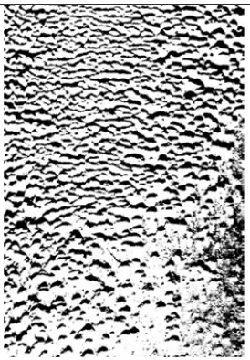
Flow-Accelerated Corrosion
Summary/Appearance
Inside surface: The corroded surface often exhibits a shiny black color typical of very thin magnetite. Where FAC is minor or just initiating, a series of pit-like features is evident on the surface. Where the FAC is most severe, the surface takes on a continuous scalloped or orange-peel appearance.
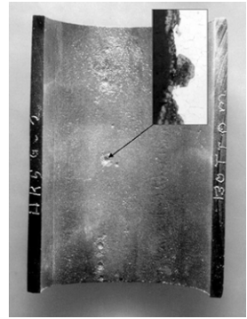
Pitting in Water-Touched Tubes
Summary/Appearance
Inside surface: Damage to affected surfaces tends to be deep, relative to the area. Pit sites may be open or filled with deposits, depending on the circumstances.